 |
| Compiler phases of Jikes RVM |
This post continues from JikesRVM Optimizing (JIT) Compiler - I
6. OptimizationPlanCompositeElement
6.1.
LinearScan – Handles
the linear scan register allocation.
6.2.
GCP – Handles Global
Code Placement. Comes in two variants. One is, Loop
Invariant Code Motion (LICM),
which is applied to HIR and LIR. The other is, Global
Common Sub Expression Elimination (GCSE),
which is applied only to LIR and before LICM. These run on static
single assignment form (SSA form). SSA form is a property of IR that
states that each variable is assigned exactly once. Utility functions
of SSA form are handled by the class SSA.
These GCP algorithms use the dominator tree to determine the
positions for operations. However,
SSA, by default is disabled in the optimization compiler, as it is
currently buggy.
6.3. SSATuneup – Places the IR in SSA form, and
cleans up by performing a set of simple optimizations.
6.4.
RegisterAllocator – The
driver routine for register allocation. The constructor initially
prepares for the allocation, and then performs the allocation using
the live information.
6.5. LoadElimination – Implements the redundant
load elimination.
6.6. LiveRangeSplitting – Performed at the end
of SSA in LIR. This performs live range splitting, when they enter
and exit the loop bodies by normal/unexceptional control flow, also
splitting on edges to and from infrequent code.
6.7. RedundantBranchElimination – Based on the
SSA form, global value numbers, and dominance relationships, the
below conditions are considered to be sufficient for a branch to be
eliminated as redundant.
* It has the same value number as another conditional
branch, and hence it is found to be equivalent to that branch.
* Target of taken branch of the other condition branch
(cb2) dominates the condition branch (cb1) under consideration,
making the target block having exactly one in edge.
* Non-taken continuation of cb2 dominates cb1, and the
continuation block has exactly one in edge.
6.8.
ConvertLIRtoMIR
– Converts an IR object: LIR → MIR, using the
Bottom-Up Rewrite System (BURS),
which is a tree pattern matching system, for instruction selection.
The constructor proceeds to create the phase element as a composite
of the other elements, in stages as given below.
*
Reduce the LIR operator set to a core set.
*
Convert ALU operators.
*
Normalize the usage of constants.
*
Compute the liveness information, build DepGraph block by block and
perform BURS based instruction selection.
*
Complex operators expand to multiple basic blocks of MIR. Handle
them.
*
Perform Null Check Combining using validation operands. Remove all
the validation operands that are not present in the MIR.
6.9. ConvertMIRtoMC – Converts an IR object:
MIR → Final Machine Code. In the constructor, it initially performs
the final MIR expansion. Then, it performs the assembly and map
generation.
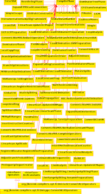
7. Subclasses of CompilerPhases
Different optimizations
of different phases are taken care by the sub classes of
CompilerPhases, which are responsible for them. Different
optimization plans of different functions will still share the same
component element objects, as every optimization plan contains a sub
set of the elements from the master plan. To avoid this overhead,
perform() of the
atomic element creates a new instance of the phase immediately before
calling the phase's perform().
The method newExecution() of
CompilerPhase is
overridden, such that, if the phase doesn't contain a state, the
phase is returned instead of its clone.
8. Operators
 |
| Class hierarchy of Operands |
OperatorList.dat in
rvm/src-generated/opt-ir
defines the HIR and LIR subsets of the Operators where the first few
define HIR only whilst the remaining define both, and
OperatorList.dat in
rvm/src-generated/opt-ir/{ARCH} (Here,
ARCH is such as ia32) defines the MIR subset. Each operator
definition consists of 5 lines given below:
SYMBOL – A
static symbol identifying the operator.
INSTRUCTION_FORMAT – The
class of Instruction format that accepts this operator.
TRAITS – Characteristics
of the operator, composed with a bit-wise OR | operator.
Valid traits are defined in the
Operators class.
IMPLDEFS – Registers
implicitly defined by the operator.
IMPLUSES - Registers
implicitly used by the operator. Here
the last two are usually applicable only to the MIR subset, which is
machine dependent.
For
example, the definition of the Floating Point
Conditional Move (FCMOV) is,
IA32_FCMOV
MIR_CondMove
none
C0_C1_C2_C3
CF_PF_ZF
|
where, for the integer addition operator, it is,
INT_ADD
Binary
commutative
|
leaving the last two lines empty.
9. Instruction Formats
Instruction formats are
defined in the package instructionFormats and each fixed length
instruction format is defined in the InstructionFormatList.dat
files in /rvm/src-generated/opt-ir
and /rvm/src-generated/opt-ir/{ARCH}
(Here, ARCH is such as ia32 and ppc).
Each entry in the InstructionFormatList.dat has 4 lines
as below.
NAME – Name of
the Instruction Format.
SIZES –
Parameters such as the number of operands defined (NUMDEFS),
defined and used (NUMDEFUSES),
and used (NUMUSES),
and additionally NUMVAR, VARDORU,
and NUMALT for
variable length instructions.
SIG –
Describing the operands. The structure is, D/DU/U NAME TYPE
[opt]. Here, D/DU/U defines
whether the operand is a def, def and use (both), or use. Type
defines the type of the operand,
as a sub class of Operand.
[opt] indicates
whether the operand is optional.
VARSIG –
Describing the repeating operands, used for variable length
instructions. The structure is NAME TYPE [PLURAL]. Here,
PLURAL is used, where NAMEs
is not the plural of NAME.
For example, let's consider the definition of NEWARRAY.
NewArray
1
0 2
"D
Result RegisterOperand" "U Type TypeOperand" "U
Size Operand"
|
Here it indicates the
three operands, one D (def), no operand of DU (def and use) type, and
two U (use), where the Def type operand is called Result,
and of type RegisterOperand,
similarly the use operands are called Type
and Size, and are of
types TypeOperand and
SizeOperand, respectively.
10. Instruction Selection
BURS is used for
instruction selection, where the rules are defined in architecture
specific files in rvm/src-generated/opt-burs/{ARCH},
where ARCH refers to
architectures such as ia32 (example files: PPC_Alu32.rules,
PPC_Alu64.rules, PPC_Common.rules, PPC_Mem32.rules, and
PPC_Mem64.rules) or ppc (example files: IA32.rules, IA32_SSE2.rules,
and IA32_x87.rules).
Each rule is defined by an entry of four lines, as given
below.
PRODUCTION – The
format is “non-terminal: rule”,
where this is the tree pattern to be matched. Non-terminal
denotes a value, followed by a colon, and followed by a dependence
tree producing that value.
COST – The
additional cost due to matching the given pattern.
FLAGS – Defined
in the auto-generated class BURS_TreeNode.
The below can be the flags.
* NOFLAGS –
No operation performed in this
production.
* EMIT_INSTRUCTION – Instructions
are emitted in this production.
* LEFT_CHILD_FIRST
– The left hand side of the
production is visited first.
* RIGHT_CHILD_FIRST
– The right
hand side first.
* TEMPLATE:
The code to be emitted.
Floating point load is defined below as an example.
Fpload:
FLOAT_LOAD(riv, riv)
0
EMIT_INSTRUCTION
pushMO(MO_L(P(p),
DW));
|
Jburg, a bottom-up rewrite machine generator for
Java, is a compiler construction tool, that is used for instruction
selection, converting the tree structure representation of the
program into a machine code.


